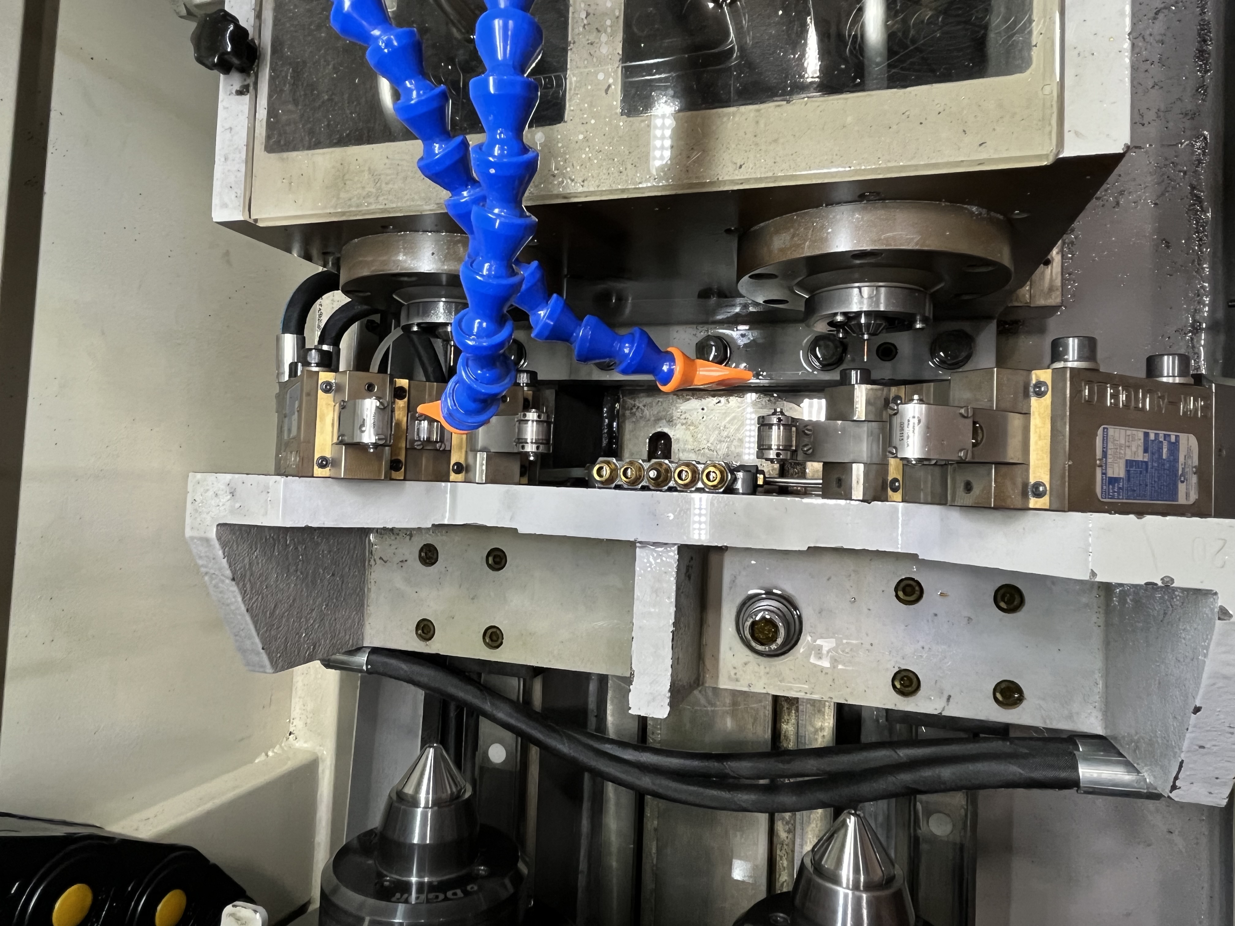
Why Chip Clogging Is the #1 Problem
After dealing with chip clogging on maybe fifty different jobs across gun drilling and BTA, three root causes keep showing up. Chip clogging accounts for roughly 60% of all troubleshooting calls I handle. When chips pack in the flute or bore, coolant flow stops, torque spikes, and the tool breaks within seconds.
The mechanism is simple: the drill generates chips faster than the coolant stream pushes them out of the bore. The chips accumulate, jam against the drill body, and block the chip flute entirely. Once the flute is blocked, coolant cannot reach the cutting edge and the drill fails almost instantly.
Root Cause 1: Insufficient Coolant Pressure
This is the most common cause, accounting for about 50% of all clogging events I have investigated. If the pressure at the drill tip drops below what the tool needs for that diameter, the chips stop moving and pack up behind the tool.
The required pressure depends on the drill diameter. For a 6 mm gun drill I typically run 85-105 bar (1200-1500 psi). Drop below 70 bar (1000 psi) and chip evacuation becomes unreliable. For larger diameters above 12 mm, the pressure requirement drops to 40-60 bar because the chip flute is larger relative to the chip volume.
| Drill Diameter (mm) | Minimum Pressure (bar) | Typical Operating Pressure (bar) |
|---|---|---|
| 3-5 | 100-140 | 120-180 |
| 6-8 | 70-100 | 85-120 |
| 9-12 | 50-80 | 70-100 |
| 13-20 | 30-50 | 40-70 |
I check the pressure at the tool tip, not at the pump gauge. The pump gauge can read 30-50% higher than the actual pressure at the drill tip due to restrictions in the rotating union, drill tube, and coolant holes. I have seen machines where the pump showed 100 bar but the tool tip only saw 55 bar because of a partially clogged filter.
If the pressure is adequate but clogging persists, I check the flow rate. A gun drill needs a minimum coolant velocity of 10 m/s through the chip flute to transport chips. I calculate the flow rate from the fluid velocity and the flute cross-sectional area. If the velocity is below 10 m/s, the chips settle instead of flowing out.
Root Cause 2: Wrong Chip Shape
The chip shape must be compatible with the flute geometry. Chips need to be short and broken into segments small enough to pass through the flute without jamming.
If the feed rate is too low, the chips form long stringy ribbons that tangle and block the flute. The solution is to increase the feed rate until the chips break into short segments. I increase feed in 10% increments until the chip shape changes from strings to crescents.
If the feed rate is too high, the chips form fine powder or dust. This indicates the cutting edge is overloaded and the chip is fracturing instead of shearing. Fine powder packs densely and blocks the flute faster than larger chips. I reduce feed by 10-15% when I see powder.
The ideal chip for gun drilling in steel is a short crescent or comma shape, 2-5 mm long and 0.05-0.15 mm thick. The chip should curl tightly and break under its own curvature.
| Chip Shape | Diagnosis | Feed Adjustment |
|---|---|---|
| Long stringy ribbon | Feed too low | Increase 10-15% |
| Short crescent (2-5 mm) | Optimal | No change |
| Fine powder or dust | Feed too high or tool dull | Decrease 10-15% or replace tool |
| Large heavy chips | Depth of cut too high | Reduce peck depth |
Root Cause 3: Guide Bushing Wear
This one I overlooked for years. A worn guide bushing lets the drill wobble just enough at the entry point to disrupt chip flow into the flute. The wobble creates a gap between the drill and the bushing that chips can enter and pack into.
The result is a clog that forms not at the cutting edge but at the bushing exit. The chips get wedged between the drill body and the bushing wall, which restricts the drill rotation and blocks the chip return path.
I check the guide bushing clearance with a bore gauge. The clearance between the bushing ID and the drill OD should be 0.005-0.015 mm for gun drilling. At 0.03 mm clearance, the drill starts to wobble. At 0.05 mm, chip clogging becomes likely.
Replace the bushing at the first sign of wear and the clogging often stops immediately. I have seen this happen multiple times: a machine with chronic clogging problems gets a new bushing and runs perfectly for months.
How to Diagnose Quickly
You do not need fancy instruments. Follow this sequence:
Start with the guide bushing. Take it out and inspect the bore visually. If you see a polished wear band or scoring, replace it and test. If the clogging stops, the bushing was the cause.
Check coolant pressure at the tool tip. If the bushing is good, the next suspect is pressure. Connect a pressure gauge at the drill holder, not the pump. That reading can be 30% off if there is a restriction in the system.
Look at the chips. If pressure checks out, examine the chips from the last cut. Long stringy chips mean feed is too low. Fine powder means feed is too high or the tool is dull. Short crescents mean the parameters are correct and the problem is elsewhere – likely a mechanical restriction in the drill or coolant line.
Preventing Chip Clogging
Prevention is more effective than troubleshooting. I maintain a clean coolant system with filters changed before the pressure differential reaches 1.5 bar. I keep guide bushings in good condition and replace them at the first sign of wear. I set feed rates to produce short broken chips for each material.
The most important preventive measure is monitoring chip shape during every cut. A change in chip shape is the earliest warning of a clogging event. If I see chips start to lengthen during a cut, I have about 5-10 seconds before the flute clogs. I stop the cycle and retract the drill before the clog solidifies.
Key Takeaways
- Insufficient coolant pressure causes 50% of chip clogging events.
- Required pressure ranges from 40 bar (large diameters) to 140 bar (small diameters).
- Long stringy chips indicate feed is too low; fine powder indicates feed is too high.
- A worn guide bushing can cause clogging even with adequate pressure and correct feed.
- Stop the cycle at the first sign of chip shape change to prevent tool breakage.