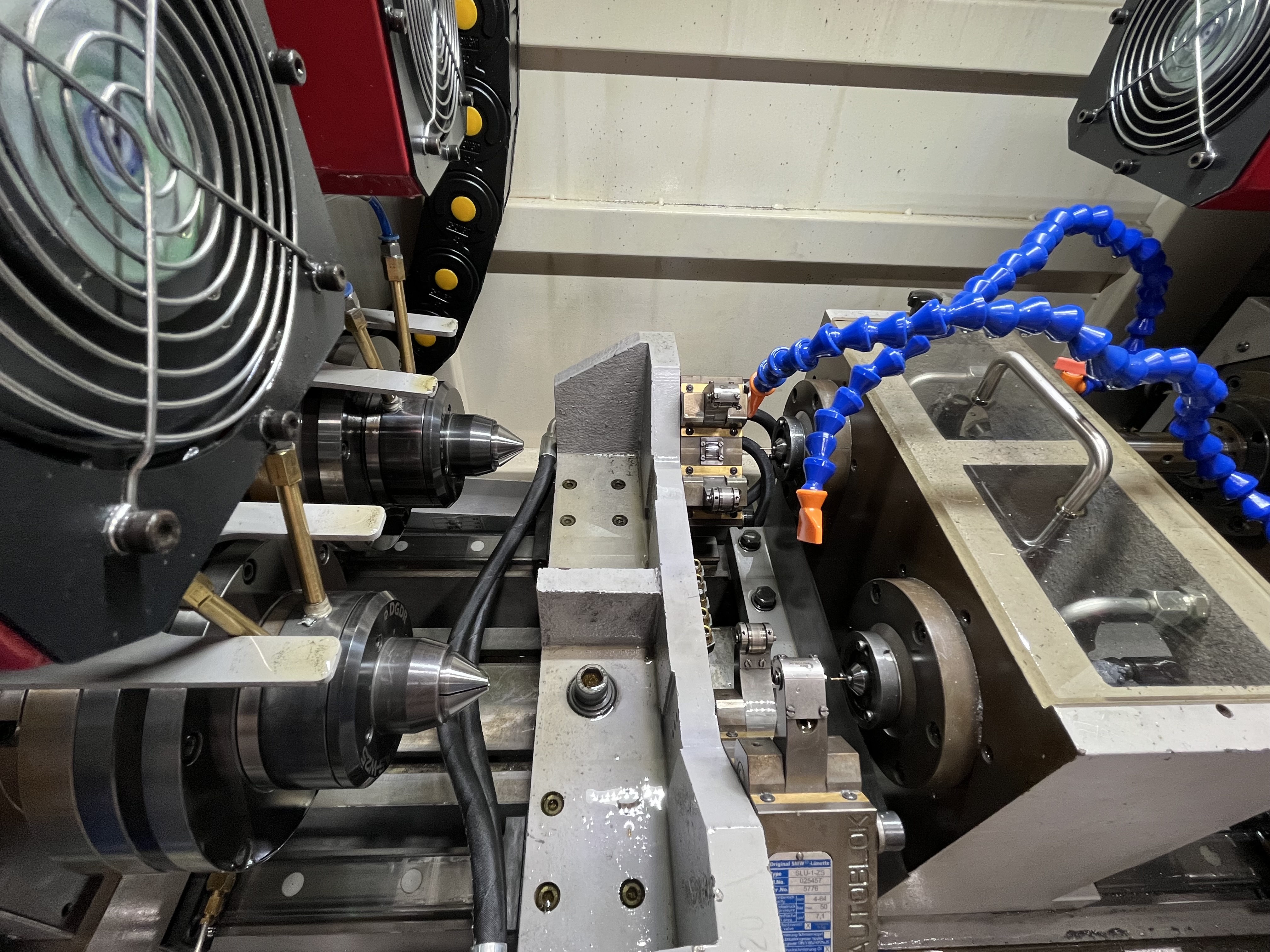
I examine every broken gun drill to figure out what went wrong. A broken drill is not trash — it is evidence. The break pattern, the fracture surface, and the location of the break all tell you something about the cause. I have learned more about deep hole drilling from examining broken tools than from any textbook.
Problem Description
Gun drills break for many reasons, but the break itself is the end result of a chain of events. The drill does not snap spontaneously. Something causes the load to exceed the strength of the drill body. The break pattern preserves information about what that something was.
The challenge is that most operators throw the broken drill in the scrap bin and put in a new one. The same problem then repeats because the root cause was never identified. A systematic examination takes five minutes and prevents the next breakage.
Break Pattern Analysis
| Break Pattern | Primary Cause | Secondary Causes to Check |
|---|---|---|
| Clean break at tip | Chip packing overload | Coolant pressure, peck cycle |
| Spiral fracture | Fatigue from vibration | Steady rests, spindle speed, bushing fit |
| Break at bushing exit | Misalignment | Bushing alignment, spindle-to-bushing axis |
| Shattered tip | Impact | Hard spots, cross holes, chip jamming |
| Break at shank | Overtightening or bending | Holder condition, feed axis alignment |
Clean Break at the Tip
A clean, flat break near the tip of the drill, typically within 10-30mm of the cutting edge, indicates an overload failure. The drill was loaded beyond its torsional or bending strength and snapped at its weakest cross-section. The most common cause I have seen is chip packing in the flute.
When chips pack in the flute, they lock the drill in the bore. The spindle keeps turning, the torque rises to the stall limit, and the drill twists off. The fracture surface shows a torsional shear pattern — a flat face with a small rough area at the center.
I check coolant pressure at the tool tip when I see this pattern. If the pressure is below 30 bar for a 6-10mm gun drill, the chips were not being evacuated. The fix is increasing coolant pressure or adding a peck cycle that retracts the drill every 50-80mm to clear chips.
Spiral Fracture
A spiral fracture that runs along the drill body at roughly 45 degrees to the axis is a fatigue failure. The drill was bending cyclically during the cut, and the alternating stress caused a fatigue crack that propagated over time. The fracture surface shows beach marks — concentric rings that mark the crack front at different stages.
Spiral fractures are caused by vibration. The drill whips inside the bore because the support is inadequate. I see this most often on long, slender drills with length-to-diameter ratios above 50:1. A 6mm drill drilling 400mm deep has a ratio of 67:1 and requires steady rest support.
The fix is adding support closer to the cutting zone. I use steady rests at intervals of no more than 30-40 times the drill diameter. For a 6mm drill, that means a steady rest every 180-240mm. I also check the spindle speed to make sure it is not hitting a resonant frequency of the drill.
Break at Guide Bushing Exit
A break at or near the guide bushing exit is a misalignment failure. The drill was bending at the bushing because the bushing centerline did not match the spindle centerline. The bending stress at the bushing exit exceeded the drill strength.
I check the bushing alignment with a test bar and indicator. The bushing should be aligned to the spindle within 0.02mm total indicated runout. If the alignment is off, I adjust the bushing holder and retest.
Bushing wear also contributes. A worn bushing with 0.05mm or more clearance lets the drill wobble, which creates bending stress at the bushing exit. I replace bushings when the ID wears more than 0.02mm oversize.
Shattered Tip
A shattered cutting edge and guide pads mean impact. The drill hit something that it could not cut through. The most common causes are hard spots in the material, the edge of a cross hole, or a chip that was jammed between the drill and the bore wall.
I check the material for hard spots when I see a shattered tip. A hardness test on the workpiece near the break point confirms whether the material was within spec. I also check for cross holes that intersect the bore path. If a cross hole exists, I reduce the feed by 50% when the drill approaches the hole depth.
| Impact Source | Detection Method | Prevention |
|---|---|---|
| Material hard spot | Hardness test at break point | Request material certs |
| Cross hole edge | Blueprint review | Reduce feed approaching hole depth |
| Trapped chip | Examine bore for chip marks | Improve chip evacuation |
Fracture Surface Examination
The fracture surface itself holds clues. I examine the break face under 10-20x magnification and look for specific features that identify the failure mode.
A torsional overload break shows a flat, granular fracture surface with a shear lip at one edge. The surface is perpendicular to the drill axis. The shear lip is the last point of material separation and indicates which direction the drill was twisting.
A fatigue fracture shows two distinct zones. The first zone is a smooth, rubbed area where the crack propagated slowly under cyclic loading. This zone may show beach marks or striations. The second zone is rough and granular where the remaining material failed suddenly. The ratio of smooth area to rough area tells me whether the fatigue crack was caught early or late.
| Fracture Surface Feature | Failure Mode | Action |
|---|---|---|
| Flat, granular, shear lip | Torsional overload | Improve chip evacuation |
| Smooth zone + rough zone | Fatigue | Reduce vibration |
| Multiple crack origins | High cycle fatigue | Change speed, add support |
| Single crack origin with beach marks | Low cycle fatigue | Check for overload events |
| Shattered, multiple fragments | Impact | Check material and cross holes |
I photograph the fracture surface and store the image in the breakage log. The image is useful for comparison with future breakages and for discussions with the tool supplier.
Documentation
I record every breakage in a log with the same fields I described in the documenting-problems article. The break pattern is a required field. After six months, I can look at the log and see which break types are most common and whether the prevention actions are working.
Key Takeaways
- Clean break at the tip means chip packing overload — check coolant pressure and peck cycle.
- Spiral fracture means fatigue from vibration — add steady rests at 30-40x drill diameter intervals.
- Break at the bushing exit means misalignment — check bushing alignment within 0.02mm TIR.
- Shattered tip means impact from hard spots or cross holes — reduce feed approaching intersections.
- Document every break pattern in a log and review it monthly for recurring patterns.