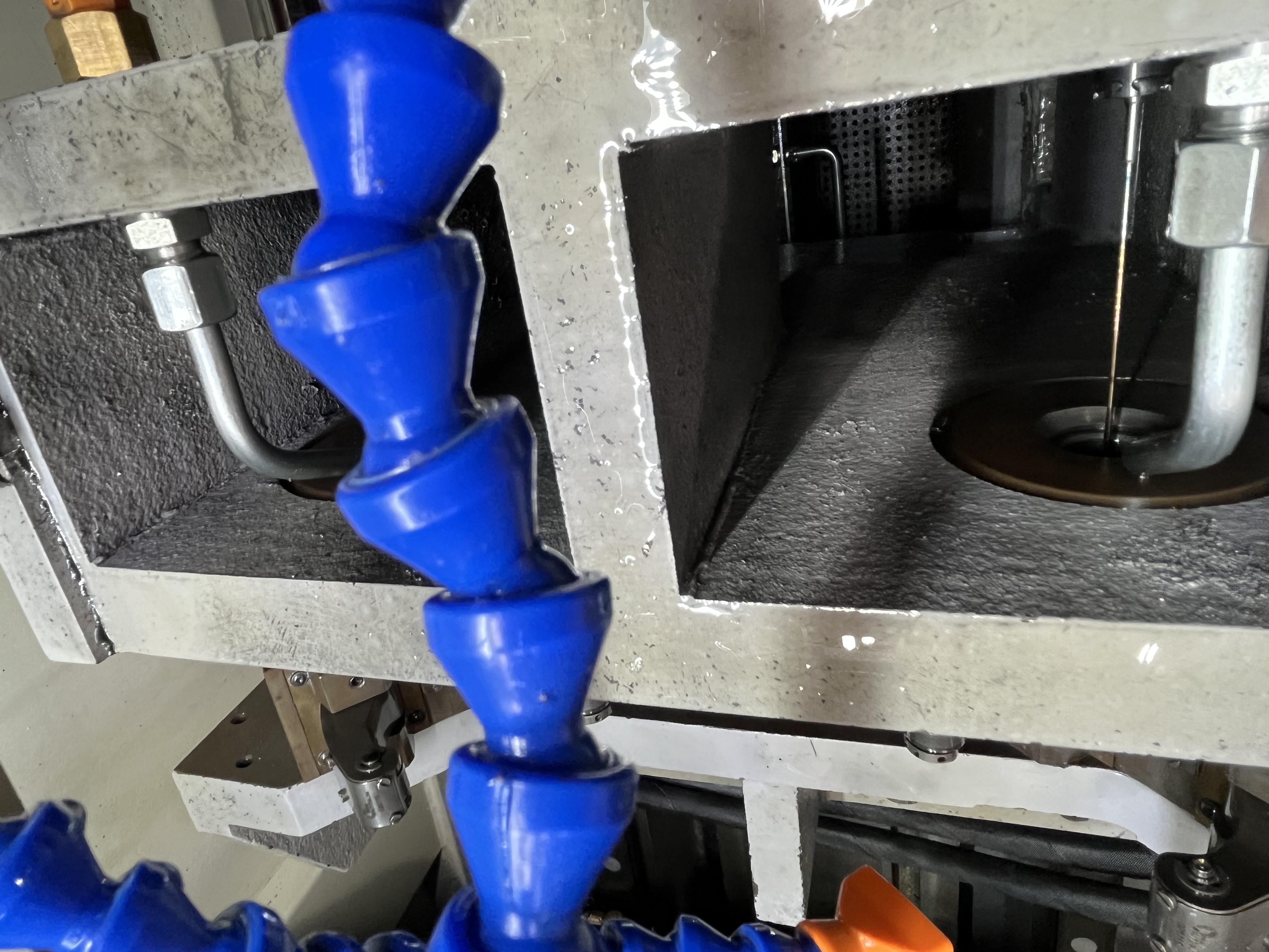
I inspect every gun drill before it goes into production and after every 20-50 holes depending on the material. Recognizing tool wear patterns helps me change tools before they break and identify the root cause of accelerated wear. The wear pattern tells me whether the parameters are right, the material is consistent, and the machine is aligned.
Problem Description
Tool wear in gun drilling is progressive. The cutting edge starts sharp and gradually rounds, chips, or wears away. The rate of wear depends on cutting speed, feed, material hardness, coolant condition, and machine alignment. When one of these factors is wrong, the wear accelerates and the tool fails prematurely.
The challenge is distinguishing normal wear from abnormal wear. Normal wear happens gradually and predictably. Abnormal wear happens quickly and signals a problem that needs correction. The wear pattern at the end of the tool’s life tells you which category it fell into.
Flank Wear
Flank wear is the most common wear type in gun drilling. The cutting edge wears from abrasive contact with the workpiece material. Normal flank wear is an even, flat wear band along the full length of the cutting edge.
| Wear Characteristic | Interpretation | Action |
|---|---|---|
| Even wear, full cutting edge | Normal abrasive wear | Continue until wear limit |
| Uneven wear, one side more | Misalignment or runout | Check bushing alignment and holder TIR |
| Heavy wear at outer corner | Speed too high for material | Reduce cutting speed by 10-15% |
| Heavy wear near center | Feed too low, rubbing | Increase feed to 0.015 mm/rev minimum |
I replace the tool when flank wear reaches 0.3mm on the cutting edge. This limit works well for carbide gun drills on steel and stainless steel. For cast iron, I use a 0.4mm limit because the wear mechanism is less aggressive on the tool edge.
I measure flank wear with a 10x magnifier or a toolmaker’s microscope. The measurement is taken at the midpoint of the cutting edge. If the wear is uneven, I measure at the heaviest point and investigate the cause.
Chipping
Chipping is small pieces broken off the cutting edge. The chips create sharp notches in the edge that degrade surface finish and accelerate further wear. A chipped edge produces visible marks on the bore surface within a few holes.
| Chip Size | Typical Cause | Prevention |
|---|---|---|
| Microchipping (< 0.1mm) | Interrupted cut, vibration | Add steady rest, reduce feed |
| Moderate chipping (0.1-0.3mm) | Hard inclusion in material | Check material cert, request test |
| Large chipping (> 0.3mm) | Impact, cross hole edge | Reduce feed at cross hole depth |
I replace the tool at the first sign of chipping. Running a chipped tool produces bad holes and risks catastrophic breakage when the chip propagates across the full edge. A chipped tool that runs for 10 more holes will have a much larger chip by the end.
Chipping in the same location on consecutive tools points to a consistent problem. I check for a hard spot in the material at that depth or a vibration mode that peaks at that engagement.
Built-Up Edge
Built-up edge (BUE) is workpiece material that welds to the cutting edge during machining. It is common in aluminum, low-carbon steel, and stainless steel. BUE changes the effective tool geometry and degrades surface finish.
I identify BUE by its appearance under magnification. It looks like a smear of material on the cutting edge rather than a wear scar. It is often the same color as the workpiece material. BUE is softer than the carbide and can be scraped off with a pick.
BUE forms when the cutting temperature is high enough to soften the workpiece material but not high enough to soften the carbide. The softened material welds to the edge under pressure. I prevent BUE by increasing cutting speed to raise the temperature past the welding zone, or by improving coolant lubricity with higher concentration.
| Material | BUE Tendency | Speed Adjustment | Coolant Concentration |
|---|---|---|---|
| Aluminum 6061 | High | Increase by 20% | 8-10% |
| 1018 steel | Moderate | Increase by 10% | 7-9% |
| 304 stainless | High | Increase by 15%, use higher feed | 10-12% |
| 4140 steel | Low | No adjustment needed | 6-8% |
Notch Wear
Notch wear is localized wear at the depth of cut line on the cutting edge. The abrasive action of the work-hardened surface layer creates a groove or notch at the point where the cutting edge meets the original workpiece surface. This is most common on work-hardening materials like 304 and 316 stainless steel.
I measure notch wear with a microscope. Normal notch wear is a shallow groove less than 0.1mm deep after 50 holes. Accelerated notch wear reaches 0.2mm in 10-20 holes and signals a problem.
The notch weakens the cutting edge and can cause a break at the notch location. I replace the tool when the notch reaches 0.2mm depth. Prevention options include using a tool grade with higher edge toughness, reducing feed by 10%, or using a wiper edge geometry.
Tracking Tool Life
I track tool life for every job using a simple spreadsheet. The sheet records the tool serial number, the number of holes drilled, and the wear measurement at removal. After 10-20 tools, a pattern emerges for the expected tool life at the current parameters.
| Material | Typical Tool Life (holes) | Wear at Removal |
|---|---|---|
| 1018 steel | 80-120 | 0.25-0.30mm flank wear |
| 4140 steel | 50-80 | 0.25-0.30mm flank wear |
| 304 stainless | 30-50 | 0.20-0.25mm flank wear |
| 6061 aluminum | 150-250 | 0.20-0.25mm flank wear |
I replace tools based on hole count when the wear pattern is consistent. This prevents running a worn tool that produces bad holes. I spot-check every 10th tool visually to confirm the pattern has not changed.
Key Takeaways
- Even flank wear up to 0.3mm is normal; uneven wear indicates misalignment or runout.
- Replace the tool at the first sign of chipping to prevent catastrophic breakage.
- Increase cutting speed and coolant concentration to prevent built-up edge.
- Notch wear at 0.2mm depth on work-hardening materials requires tool replacement.
- Track tool life by hole count and verify with periodic visual inspection.