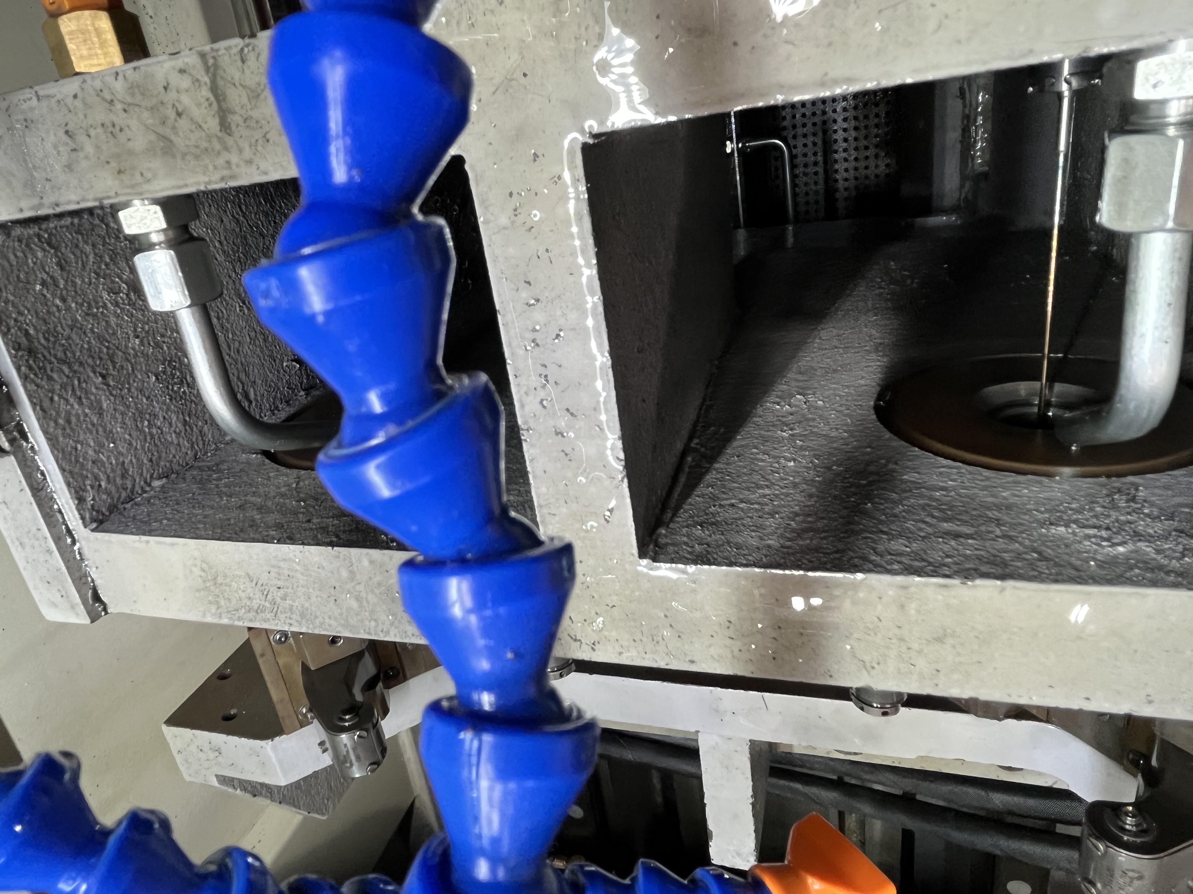
Heat buildup in thin wall drilling is a problem that affects both the process and the part quality. The thin wall cannot conduct heat away from the cutting zone as fast as a solid section can. The heat accumulates locally, causing thermal expansion that changes the bore diameter during the cut and leaves residual stress in the part afterward.
Problem Description
When heat accumulates in a thin wall section, the material expands at the cutting zone. The bore diameter temporarily shrinks as the expanded material pushes inward. The drill then cuts a larger diameter than intended because it is cutting into the expanded material. When the part cools, the bore spring back undersize or out of round.
I have measured this effect on thin wall tubes with 2-4mm wall thickness. The bore diameter during cutting can be 0.03-0.08mm larger than the final diameter after cooling. For a part with a 0.05mm diameter tolerance, that swing consumes the entire tolerance band.
The secondary problem is metallurgical damage. Excessive heat can change the surface hardness and microstructure of the bore. I have seen bores that showed hardness variations of 5-10 HRC across the length because of uneven heat buildup during drilling.
Factors That Affect Heat Buildup
| Factor | Effect on Heat | Thin Wall Adjustment |
|---|---|---|
| Wall thickness | Thinner walls conduct less heat | Below 5mm wall requires attention |
| Material thermal conductivity | Low conductivity traps heat | Stainless steel is worse than aluminum |
| Cutting speed | Higher speed = more heat per second | Reduce by 10-20% |
| Coolant flow | Removes heat from cutting zone | Run at maximum available flow |
| Drill contact length | Longer contact = more friction | Use gun drills with smaller pad areas |
The material matters significantly. Aluminum conducts heat well and dissipates it through the part quickly. Stainless steel conducts heat poorly, so the heat stays in the cutting zone. I have drilled 304 stainless tubes with 3mm walls where the bore temperature at the cutting zone reached 200 degrees while the rest of the part stayed at 30 degrees.
Heat Management Strategies
Coolant Flow
High coolant flow is the most effective way to remove heat from the cutting zone. The coolant absorbs heat at the cutting edge and carries it away. I run the coolant at maximum flow for thin wall work, typically 60-100 L/min for a 10mm gun drill.
The coolant temperature also matters. Coolant at 25 degrees removes more heat than coolant at 35 degrees because the temperature gradient drives heat transfer. I run the chiller at maximum capacity when drilling thin wall parts.
Peck Cycle
The peck cycle provides periodic cooling breaks. Each retract stops the cutting and lets the coolant flush the cutting zone. The coolant flow during the retract is at maximum pressure and removes the accumulated heat.
I use shorter pecks for thin wall work. For a solid bar, I use 100mm pecks. For thin wall parts under 5mm wall thickness, I reduce the peck depth to 30-50mm. The shorter peck increases cycle time but prevents heat buildup.
| Wall Thickness | Recommended Peck Depth | Coolant Flow Setting |
|---|---|---|
| Above 10mm | 80-100mm | Standard flow |
| 5-10mm | 50-80mm | 80% of maximum |
| 3-5mm | 30-50mm | 100% of maximum |
| Below 3mm | 15-30mm | 100% of maximum + external cooling |
Cutting Speed and Feed
Cutting speed drives heat generation. Each meter per minute of cutting speed generates a specific amount of heat at the shear zone. Reducing speed directly reduces the heat input.
I reduce cutting speed by 10-20% for thin wall drilling compared to solid material. For a 10mm carbide gun drill in 4140 steel, I normally run 80 m/min on solid material and reduce to 65 m/min on a 3mm wall tube.
Feed rate has a more complex effect. A higher feed generates more heat per second because the material removal rate is higher. But the part spends less time in the machine, so the total heat exposure is shorter. I keep the feed at the normal level for the material and manage heat through coolant flow and peck cycle.
Material-Specific Strategies
Different materials require different heat management approaches. Aluminum conducts heat well and dissipates it rapidly, but the material is sensitive to thermal expansion. A 6061 aluminum tube with 3mm wall can expand by 0.03mm in diameter for every 10 degrees of temperature rise.
| Material | Thermal Conductivity | Heat Risk | Strategy |
|---|---|---|---|
| 6061 aluminum | High (167 W/mK) | Thermal expansion | High coolant flow, measure after cooling |
| 4140 steel | Medium (42 W/mK) | Moderate | Standard peck, monitor temperature |
| 304 stainless | Low (16 W/mK) | High | Short pecks, max coolant, reduced speed |
| Titanium Ti-6Al-4V | Very low (7 W/mK) | Very high | Very short pecks, low speed, high coolant |
For stainless steel and titanium, the heat stays localized at the cutting zone because the material conducts it away slowly. I have measured cutting zone temperatures of 250 degrees on 304 stainless with a 2mm wall. The heat does not dissipate into the rest of the part; it stays where the drill is cutting and builds up with each pass.
For these materials, I use the minimum peck depth that keeps the drill cutting continuously. A peck depth of 15-20mm on a 2mm wall stainless tube generates less heat per peck than a 30mm depth and allows more cooling time between pecks.
Measuring and Verifying
I check the part temperature after drilling by touching the bore wall near the exit end. If it is too hot to hold (above 50 degrees), the heat management needs improvement.
For critical parts, I use an infrared thermometer to measure the bore temperature at the exit during drilling. A reading above 100 degrees means the peck depth needs to be reduced or coolant flow needs to be increased.
I let the part cool to room temperature before measuring the bore diameter. Measuring a hot part gives a false reading that is 0.02-0.05mm larger than the final size.
Key Takeaways
- Thin walls below 5mm cannot conduct heat away fast enough and need active heat management.
- Run coolant at maximum flow and use the chiller at maximum capacity for thin wall parts.
- Reduce peck depth to 30-50mm for 3-5mm wall thickness and 15-30mm for below 3mm.
- Reduce cutting speed by 10-20% for thin wall drilling compared to solid material.
- Let the part cool to room temperature before measuring bore diameter to avoid thermal expansion error.