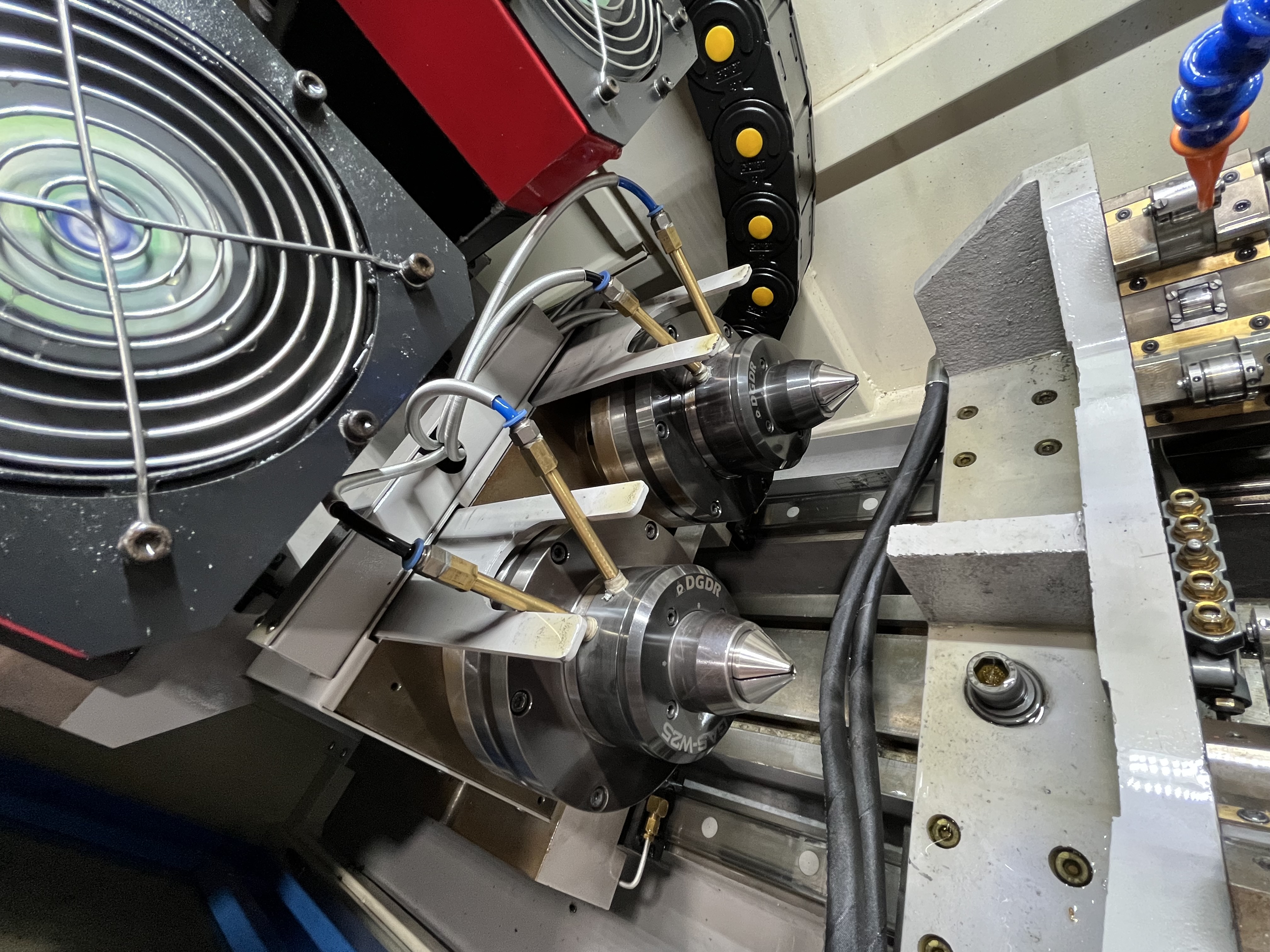
Understanding Hole Deviation
Hole deviation is one of the most frustrating problems in deep hole drilling. The drill starts on center and slowly drifts off course as it goes deeper. By the time it reaches full depth, the hole may be out of position by several millimeters.
I have seen deviation ruin parts at depths as shallow as 50mm and as deep as 2 meters. The financial impact adds up fast when you scrap a part that already has hours of machining invested.
Deviation is not random. It follows predictable patterns once you understand what causes it. That predictability is what makes prevention possible.
In my experience, deviation falls into three categories: gradual drift in one direction, sudden step changes at specific depths, and spiral or helical paths. Each type points to a different root cause.
Root Causes of Hole Deviation
Machine Misalignment
The most common cause I see is machine misalignment. The spindle axis is not perfectly parallel to the bed travel. Even a small angular error at the spindle translates into a growing offset as the drill goes deeper.
I check alignment with a test bar mounted in the spindle. I measure runout at the spindle nose and at the far end of the test bar. The reading at the far end should not exceed 0.02mm for a 300mm test bar.
| Error at Spindle | Result at 200mm Depth | Result at 500mm Depth |
|---|---|---|
| 0.01mm | 0.007mm | 0.017mm |
| 0.02mm | 0.013mm | 0.033mm |
| 0.05mm | 0.033mm | 0.083mm |
I have learned that alignment checks once a month are not enough for production machines. I check every week on machines that run 24/7.
Worn Guide Bushings
The guide bushing is the first point of support for the drill. It should hold the drill within 0.01mm of its nominal diameter. A worn bushing with 0.03mm clearance introduces wobble at the entry point.
That wobble at entry multiplies as the hole gets deeper. A 0.02mm clearance at the bushing can produce 0.1mm of deviation at 300mm depth. I replace bushings when the clearance exceeds 0.02mm for a 10mm drill.
Uneven Material Hardness
The drill bit acts like a directional tool. It steers toward the softer side of the material when faced with a hardness gradient. I have seen this most often in heat-treated parts that have a hard case on one side.
Counter-rotation is my preferred fix for this problem. The inner and outer tubes rotate in opposite directions, which cancels out the steering forces. On machines with that capability, I see consistently straighter holes at L/D ratios above 100:1.
Solutions and Prevention
Weekly Alignment Checks
I built a simple alignment check routine that takes 15 minutes per machine. The procedure uses a test bar and a dial indicator mounted on the bed. I record every reading in a logbook.
| Check Item | Frequency | Acceptable Limit |
|---|---|---|
| Spindle-to-bed parallelism | Weekly | 0.02mm / 300mm |
| Guide bushing concentricity | Weekly | 0.02mm |
| Bed level | Quarterly | 0.02mm / meter |
The logbook reveals trends. If the alignment shifts by 0.005mm from one week to the next, I know something is loosening or wearing. I investigate before it reaches the 0.02mm limit.
Proper Bushing Maintenance
I track bushing wear by measuring the internal diameter with a bore gauge. Each bushing gets measured at installation and then every 50 operating hours. The wear rate tells me when to schedule replacement.
Bushing life depends on the material being drilled. In 4140 steel at 30 HRC, I get about 200 operating hours. In aluminum, the same bushing lasts over 500 hours. In stainless steel, I am lucky to get 100 hours.
Counter-Rotation for Long Holes
For any hole with an L/D ratio over 100:1, I use counter-rotation when the machine supports it. The setup takes extra time but the improvement in straightness is dramatic.
I have measured hole deviation of 0.3mm over 600mm with counter-rotation versus 0.8mm with standard rotation on the same machine and material. The difference in straightness alone justifies the extra setup.
Entry Condition Control
The first 10mm of the hole determines the rest of the hole. I pay careful attention to the entry conditions. The spot face must be flat and perpendicular to the drill axis.
I typically run the entry feed at 70% of the normal rate for the first 3mm of penetration. This gives the drill time to establish a stable cutting action before the feed increases.
Key Takeaways
- Check machine alignment weekly, not monthly. Track trends in a logbook.
- Replace guide bushings when clearance exceeds 0.02mm. Do not wait for deviation to appear.
- Use counter-rotation for holes over 100:1 L/D ratio.
- The first 10mm of the hole determines straightness. Control entry conditions carefully.
- Material hardness gradients cause steering effects that are hard to correct after the hole starts.