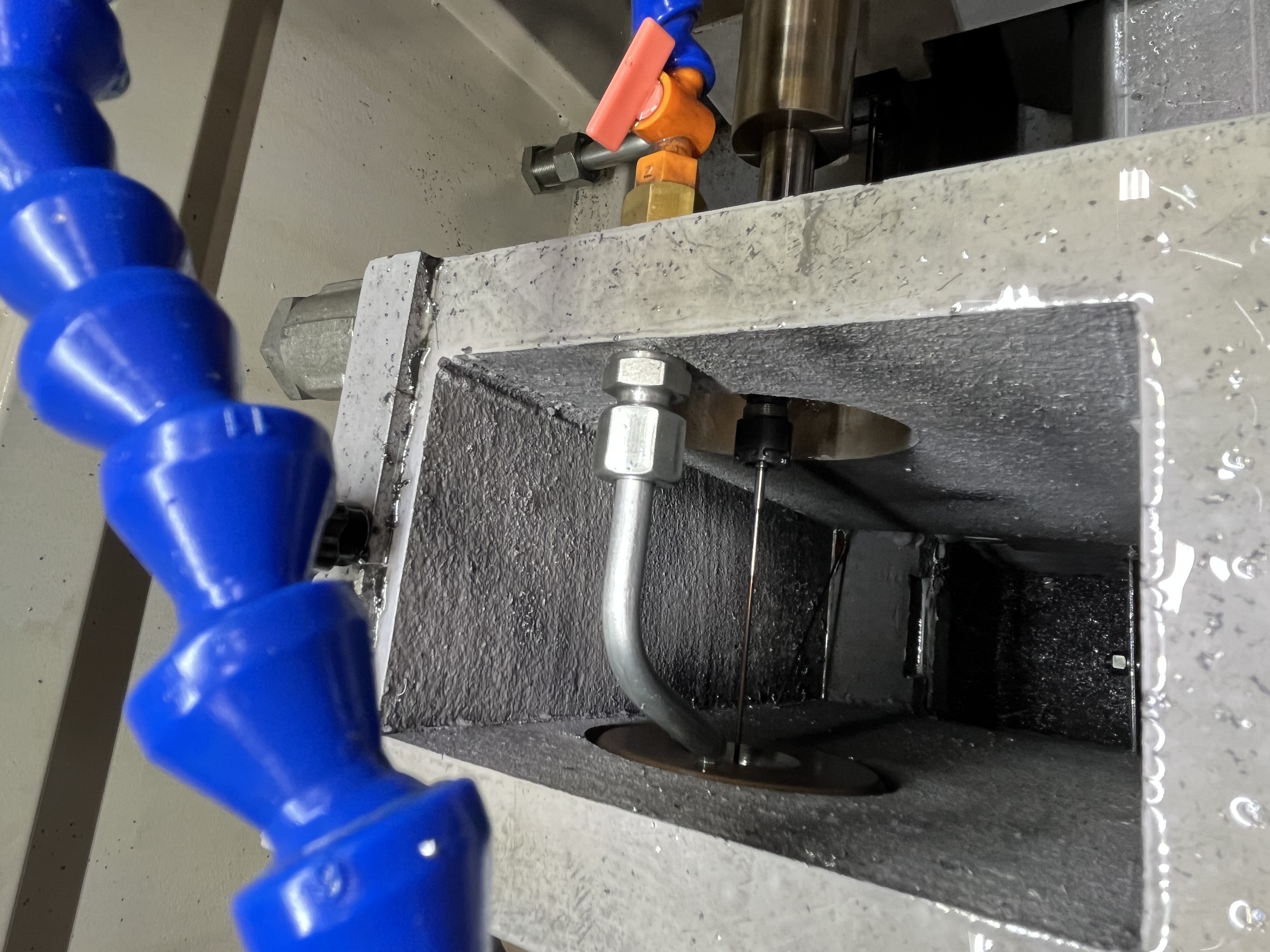
Sleeving is a repair technique I have used to salvage deep hole drilling parts when the bore was machined oversize, damaged during drilling, or worn in service. The process involves boring the damaged hole to a larger diameter and installing a thin-walled sleeve that restores the original bore size. I have saved parts worth thousands of dollars this way.
Problem Description
An oversized bore in a deep hole drilling application can mean the part is scrap. The bore diameter is outside tolerance, the surface finish is damaged, or the bore is out of round. Replacing the part entirely costs 3-5 times what a sleeving repair costs and takes longer to procure.
Sleeving works by replacing the damaged bore surface with a new, precision-machined surface. The sleeve becomes the new bore wall, and the original part provides the structural support. The repair is permanent if done correctly.
| Bore Problem | Sleeve Feasibility | Alternative |
|---|---|---|
| Machined 0.2mm oversize | Yes | Weld and re-bore |
| Damaged by broken drill | Yes, if damage is within bore | Scrap part |
| Worn oversize from use | Yes | Oversize tooling |
| Out of round (more than 0.1mm) | Yes | Line boring |
| Cracked bore wall | No | Scrap part |
Preparation
The first step is boring the damaged hole to a clean, round diameter. The bore must be straight within 0.02mm over the full length and smooth with a surface finish of Ra 1.6 or better for the sleeve to fit properly. I use a single-point boring bar on a deep hole machine or a horizontal boring mill for this step.
I measure the bored diameter at multiple depths with a bore gauge. The diameter variation should be less than 0.02mm. If the variation is larger, I take another pass with the boring bar.
The sleeve material should match or be compatible with the part material. For steel parts, I use the same grade of steel. For cast iron, I use ductile iron or steel. The sleeve material must have similar thermal expansion to the part material so the fit does not change with temperature.
Sleeve Design and Installation
I design the sleeve with a wall thickness of 2-5mm depending on the bore size. The sleeve OD is machined to provide the desired fit with the prepared bore. The sleeve ID is machined 0.5-1.0mm undersized to allow for final boring after installation.
| Bore Diameter | Recommended Sleeve Wall | Installation Method |
|---|---|---|
| 10-25mm | 2-3mm | Adhesive only |
| 25-50mm | 3-4mm | Light interference + adhesive |
| 50-100mm | 4-5mm | Interference fit + adhesive |
| 100mm+ | 5-8mm | Shrink fit + adhesive |
Interference Fit
For sleeves above 3mm wall thickness, I use an interference fit. The sleeve OD is 0.02-0.05mm larger than the bore ID. I press the sleeve into the bore using a hydraulic press or a threaded puller. The interference locks the sleeve in place and provides metal-to-metal contact for heat transfer.
The pressing force depends on the interference and the contact length. A 50mm diameter sleeve with 0.03mm interference over 200mm length requires approximately 5-10 tons of pressing force. I apply the force slowly and steadily to avoid buckling the sleeve.
Adhesive Installation
For thin sleeves under 3mm wall thickness, I use anaerobic adhesive instead of interference fit. The adhesive fills the microscopic gap between the sleeve and the bore and locks the sleeve in place. The clearance between the sleeve and bore should be 0.05-0.10mm for the adhesive to work.
I apply the adhesive to the sleeve OD and insert it into the bore with a slow twisting motion. The adhesive cures in 30-60 minutes at room temperature. I apply pressure to the sleeve during curing by threading a puller through the bore and applying light tension.
| Adhesive Type | Gap Capacity | Cure Time | Max Temperature |
|---|---|---|---|
| Loctite 638 | 0.25mm max | 60 min | 150 degrees |
| Loctite 648 | 0.15mm max | 30 min | 175 degrees |
Shrink Fit
For large bores above 100mm, I use a shrink fit. I cool the sleeve in liquid nitrogen to -196 degrees and heat the part to 150 degrees. The differential expansion provides 0.1-0.2mm clearance for assembly. When the temperatures equalize, the sleeve is locked with 0.05-0.10mm interference.
Shrink fitting requires careful safety precautions. Liquid nitrogen needs proper handling equipment and ventilation. I only use this method when the interference and wall thickness demand it.
Final Machining
After the sleeve is installed, I machine the sleeve ID to the final bore diameter. The sleeved bore can be drilled with a gun drill or BTA head if the setup is rigid enough. For most repair work, I bore the final diameter with a single-point boring tool.
I take two passes: a roughing pass leaving 0.2mm and a finishing pass to the final dimension. The surface finish on the finished bore should match the original specification, typically Ra 0.8 or better.
Limitations
Sleeving is not suitable when the remaining wall thickness around the bore is too thin. I check the minimum wall thickness between the bore and the part OD or adjacent features. The wall after sleeving must be at least 50% of the original design wall thickness.
Sleeving also requires access to the full length of the bore for boring and installation. Blind holes can be sleeved if the sleeve is split or if I use a blind-hole installation tool, but the process is more complex.
Key Takeaways
- Sleeving saves high-value parts at 20-30% of replacement cost.
- Bore the damaged hole straight within 0.02mm and Ra 1.6 or better before sleeving.
- Use interference fit for sleeves over 3mm wall thickness and adhesive for thinner sleeves.
- Machine the sleeve ID 0.5-1.0mm undersized for final boring after installation.
- Verify minimum wall thickness around the bore is at least 50% of original design before sleeving.